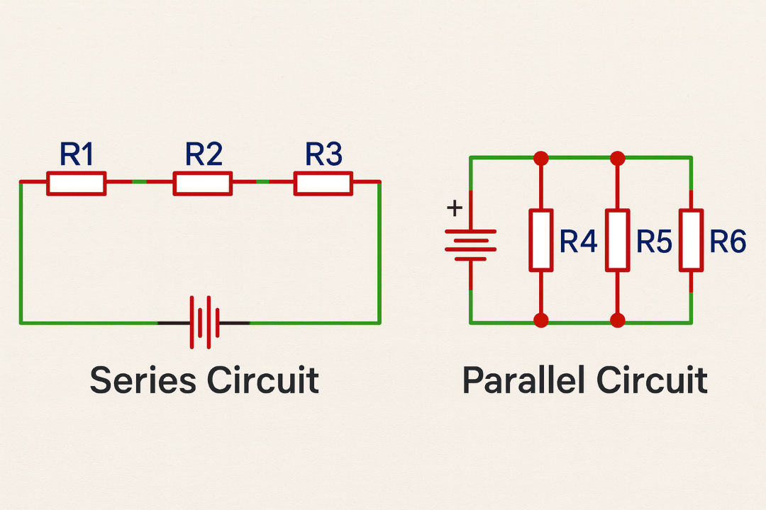
Electrical circuits are typically formed by combining components (resistors, capacitors, inductors, sources) in two fundamental topologies: series and parallel. Understanding the characteristics of each topology enables you to analyze circuits, compute equivalent resistance, voltage drops and current distribution — essential tasks for design and troubleshooting.
In a series circuit, components are connected end-to-end so that the same current flows through every element (I_total = I1 = I2 = …). The supply voltage is divided among the resistances proportionally to their values.
R_total = R1 + R2 + R3 + ...Since the same current I flows through each resistor:
V_k = I × R_kWith a 12 V source and resistors R1 = 100 Ω, R2 = 200 Ω in series:
R_total = 100 + 200 = 300 Ω
I = V / R_total = 12 / 300 = 0.04 A (40 mA)
V_R1 = I × R1 = 4 V
V_R2 = I × R2 = 8 VIn a parallel circuit, elements are connected across the same two nodes; therefore, the voltage across each branch is equal (V_total = V1 = V2 = …). The total current is the sum of branch currents.
1 / R_total = 1 / R1 + 1 / R2 + 1 / R3 + ...
For two resistors:
R_eq = (R1 × R2) / (R1 + R2)I1 = V / R1
I2 = V / R2
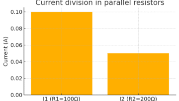
I_total = I1 + I2A 10 V source feeds two parallel resistors R1 = 100 Ω and R2 = 200 Ω:
I1 = 10 / 100 = 0.10 A
I2 = 10 / 200 = 0.05 A
I_total = 0.15 A
R_eq = 1 / (1/100 + 1/200) = 66.67 Ω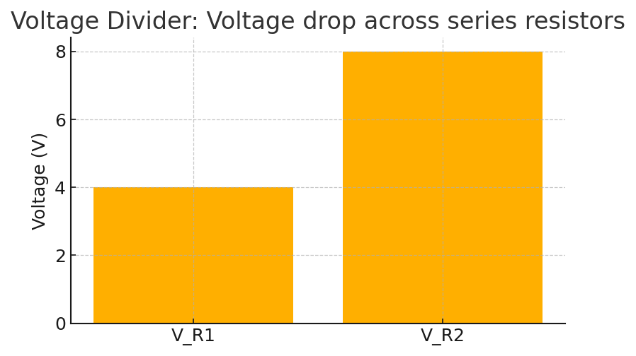
The voltage divider is a common use of series resistors — it creates a scaled voltage reference for sensors, ADC inputs, or bias networks:
V_out = V_in × (R2 / (R1 + R2)) Example: V_in = 12 V, R1 = 1 kΩ, R2 = 2 kΩ → V_out = 8 V.
Problem 1: Compute the total resistance for this network: R1 = 220 Ω in parallel with the series pair (R2 = 330 Ω + R3 = 470 Ω). (Hint: compute R2 + R3 first, then parallel with R1.)
Problem 2: Design a divider to produce 3.3 V from a 12 V source to feed a sensor drawing ~5 mA. Choose R1 and R2 so that the divider’s output impedance is low enough (e.g., divider impedance ≤ 1/10 of sensor input impedance).
Mastering series and parallel analysis is fundamental for circuit design and troubleshooting. The ability to reduce complex networks into simpler equivalents makes solving real-world electrical problems manageable and reliable.
Keywords: series circuit, parallel circuit, equivalent resistance, voltage divider, current division, basic electronics

